One of the things I’ve been interested in for the last year or so, is developing for the Atari family of 8-bit computers. I haven’t done a lot yet, but I’ve been slowly getting software, docs, and hardware to start writing code with all the tools I could possibly need.
I had already built a SIO2Arduino, and that allows me to emulate a disk drive that I can use to load the dev tools I need. Its biggest problem, however, is that it only allows you to mount one disk drive at a time. If I wanted to have any form of operating system, dev tools and my own project files, I would need to create a custom Frankenstein disk image with everything inside.
A more elegant solution, of course, would be to use something that’d allow me to emulate several drives at once. That device already exists, and it’s called SDrive-Max.
SDrive-Max
There are a few website discussing the SDrive Max project, but Atari8bit.net does a pretty good job of explaining everything you need to know about it.
Circuit-wise SDrive-Max is only slightly more complex than SIO2Arduino. You still need an Arduino, an SD-card module, and a screen, but it’s a bit harder to build considering it requires a more sophisticated display, with the touchscreen, LCD and SD card sharing some pins (or having some pretty specific arrangements).
You can of course buy the device ready to use from other Atari enthusiasts and several shops online, but it’s not a cheap thing. And considering I have all the components (more or less) to make one, I decided to give it a go.
The LCD problem
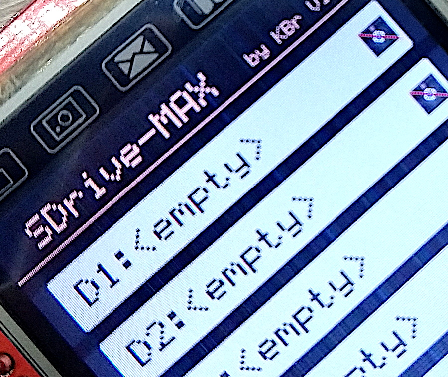
Now I knew the biggest problem was going to be the screen. While the SDriveMax project supports several popular LCDs, none of the displays I have match the specs nor the touchscreen pinout of the “officially” supported LCDs. The closest one I have, is a cheap 2.4 TFT that in theory uses the ILI934x controller, but requires what can only be described as an “alternative” initialization routine to work properly. This is something I have already talked about in my blog, but if I actually flash the SDrive firmware with its default LCD initialization I get some color bleeding and weird lines:

I haven’t found the cause yet, but considering a lot of initialization commands for the LCD are related to voltage levels and color adjistment, I’m guessing this problem is caused by a non-standard driving circuitry.
Anyway, let’s fix it!
Making things Work
SDrive-Max ‘s firmware is open source, and you can get it from kbr-net´s Git-Hub repo, so my plan is to modify the LCD initialization code, so my cheap-ass TFT display works.
To do that, the first step is to make sure I’m able to build the firmware from its source code without any changes.
Now, it’s really easy to get the code to compile provided you have access to a Linux box. You first will need to install avr-gcc and avrdude, and compile the xa cross-assembler. You can also compile SDrive from Windows, but you’ll need to modify the makefiles to make it work.
Once I was able to compile the code it was time to include the small tweaks in the display initialization that my particular TFT needs. The code that does that can be found in display.c, in the TFT_init() function. I replaced the initialization for the ILI93xx devices with this:
    delay_ms(200);
    TFT_write_cmd(ILI9341_POWER1);
    TFT_write(0x23);
    TFT_write_cmd(ILI9341_POWER2);
    TFT_write(0x10);
    TFT_write_cmd(ILI9341_VCOM1);
    TFT_write(0x3e);
    TFT_write(0x28);
    TFT_write_cmd(ILI9341_VCOM2);
    TFT_write(0x86);
    TFT_write_cmd(ILI9341_PIXEL_FORMAT);
    TFT_write(0x55);
    TFT_write_cmd(ILI9341_FRC);
    TFT_write(0x00);
    TFT_write(0x18);
    TFT_write_cmd(0xF2);
    TFT_write(0x00);
    TFT_write_cmd(ILI9341_GAMMA);
    TFT_write(0x01);
In a previous version I also had to change the touchscreen mapping in touchscreen.h, but I recently updated to the latest code in the repository and didn’t need to edit that file at all. The new version autodetects the touchscreen configuration, which is pretty sweet.
Anyway, with the changes in place, it was a matter of compiling the code and flashing it to my device with:
avrdude -p m328p -c arduino -P /dev/ttyUSB0 -b 115200 -U flash:w:SDrive.hex
If you are flashing for the first time you will need to write eeprom_writer.hex first. Then you can flash SDrive.hex.
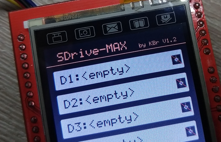
After the update this is what I got:

I still need to design and 3D-print a box for my device now, but my SDrive-Max is working wonderfully after the hack.
UPDATE:
These are the compiled binaries in case you want to test them quickly, or if you can’t compile the code yourself:
Please, Mr.E,
Could you share the firmware?
Like John I’m also interested in the “HEX” file. This makes things much easier since we are not programmers.
Thank you in advance!
Hi Joe,
I added the compiled HEX files to the bottom of the post. Let me know if they work for you.
Regards,
Hi, lately I have tried a LOT of 2.4 screens from many sellers and even though the screens display is correct the touch does not work. They claim that it is ili9341, and they send drivers for arduinoIDE but as we knows-drive max code has nothing to do with arduinoIDE and can’t be compiled from there
Hi George,
As far as I know the ILI9341 driver IC does not control the touchscreen at all, so it’s entirely possible that your screens do have the controller they claim, but the touchscreen is wired to different pins. I would advise you to check the pinout of your screen (if it’s written on the PCB) or request the pinout from the sellers.
could you share the firmware you have made for this screen to work
Hi! My changes were really minimal and documented in this post, so branching their source would be pretty much pointless. Compiling the firmware from their Git repository with my changes shouldn’t be hard. Now, if you meant the HEX file I guess I can host it here too, if that’s of any use to you or anyone else. Let me know.