
Tape recorders, computers and capture cards all seem to be happy to accept a microphone input for adding audio or voice-overs, but very few have a “line input” to overlay music or any other “strong” signal source instead.
While you can -in theory- connect a sound source there (at your own risk) you will find that in most cases you will get pretty distorted audio. This is because microphones normally work at a much lower signal level than regular “line” in/out audio, and have a DC offset to enable simple electret microphones to work with them, which is what most passive headset/desk mics actually are.
If you want to properly connect something there that is not a microphone, you need to (at the very least) attenuate the signal, and hopefully get rid of the DC offset.
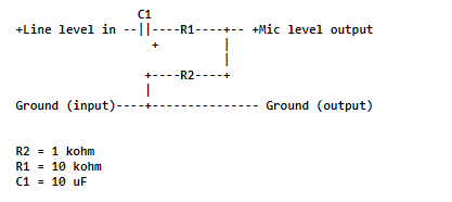
Audio attenuator “pads” exist for this kind of use case, and it’s not hard to build one yourself. This page compiles a few options for different attenuation settings and use cases. For my needs I picked the one with the -20dB and DC-offset removal.
The circuit looks like this:
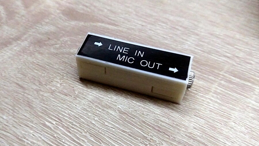
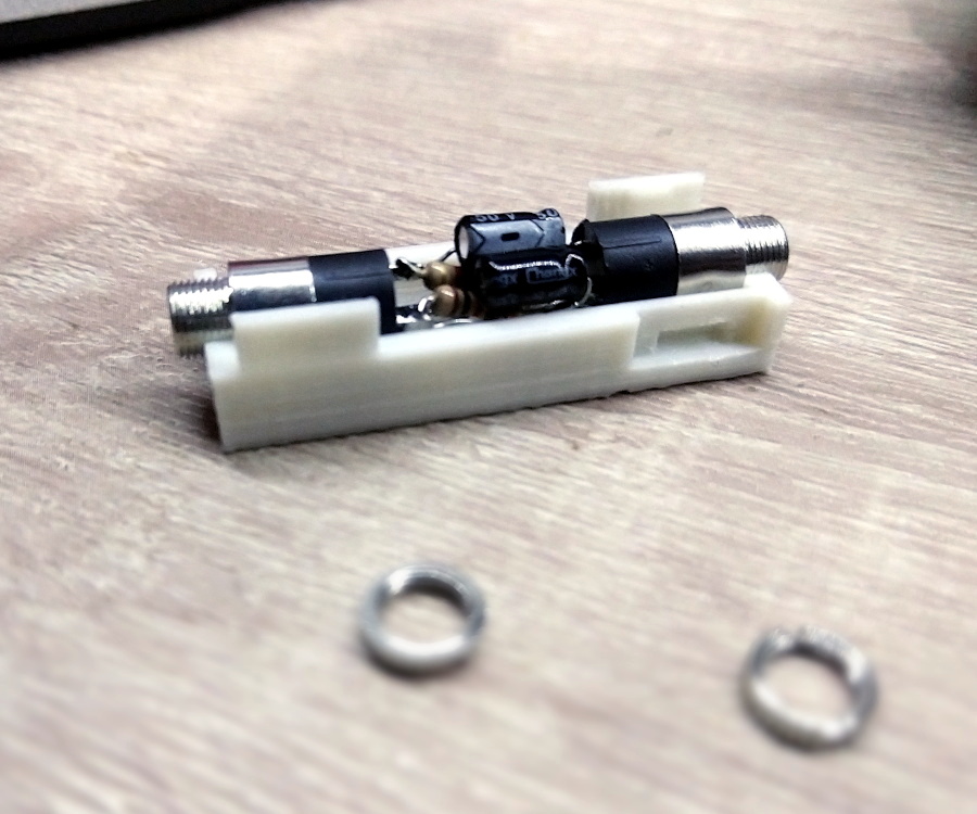
I free-form soldered this circuit and tested it on my computer, and seemed to work fine, so decided to build a small enclosure for it and 3d-print it. As usual, I’ve uploaded the model to Thingiverse.
The small case should be able to accommodate most attenuation circuits, so you can build yourself a set of different attenuators for all your audio needs.
chat gpt wants to put a 500K ohm for R1 and 3.3K ohm for R2 and a 100Nf ceramic cap to go from a line 100 ohm output to a 1M ohm mic input. the 100nF is good enough for above 3,16 HZ so… really confused, I see nobody using 500K ohm resistors in such a circuit. even after saying that it persisted in not going below 47K. is says that R1 is for the attenuation and R2 for the imbalance or something.
I wouldn’t trust ChatGPT with circuit design, at least not right now. This circuit, however, is basically a voltage divider (where the attenuation will be proportional to the ratio between both resistances) and the capacitor is for DC-blocking. There’s no resistor for balancing here (as far as I know). Now, while in theory you “could” use bigger resistors as long as the ratio is right, in practice these resistors will also have to deal with the input and output impedance of the connected devices and their actual capacity to “drive” loads (i.e: source current). The resistances picked should allow a reasonable amount of current to flow, but not enough to bring down or drown the line voltage. Now, the frequency response (for that specific value of capacitor) is an interesting question. I don’t know enough about designing attenuators (or I wouldn’t have needed to look up already designed circuits :D) but my understanding is that the capacitor will act as a DC-blocking filter in combination with the input and output impedances, so its frequency response will depend on them as well, not only the capacitor value.
Hello. I’ve seen your blog post on audio attenuator when researching form my project.
And it helped me a lot, thank you for posting it.
I have struck a wall with my project though and I wander if you can help me?
I’m building a phone based on sim7600 module which should be connected to the computer.
It looks roughly like this
(server usb)
||
+–(usb hub)–+
| |
(usb) |
( usb to ) (usb)
(jack sound) sim7600
( card ) (trrs jack)
(trrs jack) |
| |
+(swap circuit)+
The swap circuit is an attenuation circuit with 10mf capacitor and 10k resistor wired both ways and have a common ground between all connections.
What I’ve discovered is that if both sim module and usb to jack connected to the same usb hub the sim module creates interference. And it’s not static noise like humming, it’s ticking and clicking and it changes when the module performs some work.
I can not connect them to different power supplies because they both have to talk to the server.
I have tried fixing it by decoupling line to mic with transformers instead of just connecting through a capacitor and resistor, and I also removed common ground connection but it didn’t work.
Next step was to put a usb isolator between sound card and usb hub but that killed the sound comming into the sim module from the sound card probably because isolator doesn’t supply enough current.
I’m out of ideas at this point. Can you help me with that?
Sorry this diagram got scuffed. Here is the better one:
…….(server.usb)
…………||
…..+–(usb..hub)–+
…..|…………..|
…(usb)…………|
(..usb.to..)……(usb)
(jack.sound)….(sim7600)
(…card…)…(trrs.jack)
(trrs..jack)……..|
…..|…………..|
…..+(swap.circuit)+
Hi!
I’m not an audio expert but if the interference continues even with isolation in between, it could be EMI (electromagnetic interference). This seems likely, considering that the circuit is mainly an RF transceiver. In that case shielding the audio circuitry (putting it inside a metal can) could help. If that isn’t the case you may need an oscilloscope to investigate further and isolate the source of the interference, and how it’s being coupled to your audio signal.