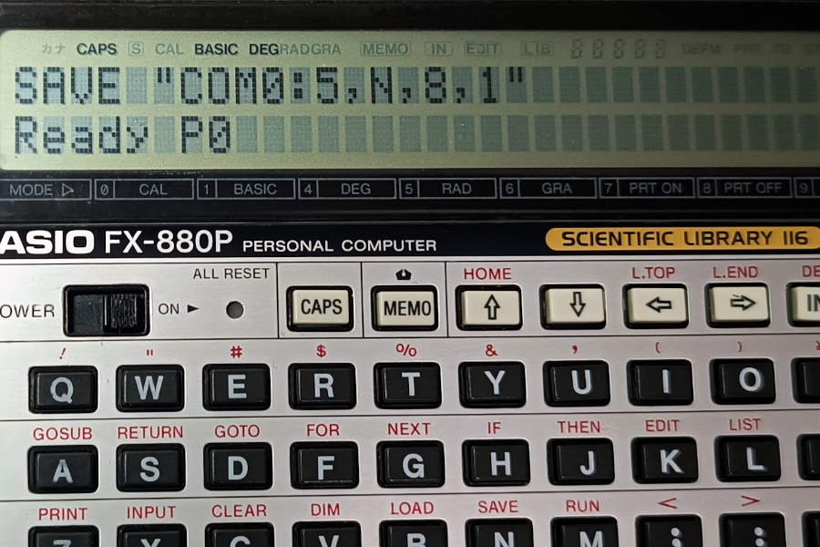
Nearly a decade ago, I wrote a post about building a serial adapter/cable for the FX-880P (and FX-850P) calculator. The design I went for was a bit over-engineered. The circuit was made of two independent parts on the same PCB; one that was a straight connection to the calculator via a 15×2, 1.27mm pitch header, and the other was a RS232-to-TTL circuit. Both halves were connected with jumpers to make the full RS232-to-Casio connection. An absolute overkill for just transferring files to/from a PC, but it gave me a lot of flexibility on how to use the circuit.
In that post I mentioned that it was possible to use something simpler, like a circuit based on a “USB-to-TTL” chip, or even an off-the-shelf USB-to-TTL adapter connected directly to the calculator side. But I never documented if it was truly feasible, and under what circumstances or considerations that could be achieved.
That was until recently, that I had a very interesting conversation with a reader of my blog that brought the idea back (Thanks Eric!)

The Idea
The simplest setup would be to use an already-made USB to TTL adapter connected directly to the calculator, provided that we have the 15×2, 1.27mm pitch header to physically plug something to its interface port. The challenge would be to find an adapter with a USB-to-TTL chip that works without issues.
Why is that? Well, back in the day the two popular chips for USB to TTL conversion, found in many adapters and cables, were the FT232 (from FTDI), and the PL2302 (from Prolific). They weren’t particularly cheap, so it didn’t take long before clone chips started appearing in the market, all sold at a fraction of their prices. And both manufacturers took measures against this; FTDI by releasing a driver that would brick clones and Prolific by phasing out their cloned product and making it so the driver would refuse to work with the oldest chips. FTDI eventually recalled the killer driver, but if you want to avoid any issues either make sure that you have a genuine chip, or avoid using them entirely.
In the past 10 years other USB-TTL chips have become popular; like the CH340G and the CP2102, and I was hoping I could do some tests with them as well.
The Setup
So I gathered some of the USB-to-TTL adapters I have, and tested them with the calculator. I found 3 different ones: One based on the FTDI FT232 chip, one based on the PL2302 chip, and one based on the CP2102 IC. I didn’t find one with the CH340G chip but I suspect it would have behaved very similar.
EDIT: Got an adapter based on the CH340G IC and works great too.
To connect them to the calculator I’m using my old home-made circuit. By removing the jumpers that bridge both sides I can connect the USB adapters directly to the calculator side. So this is what the connection looks like for all the adapters (except that with a different adapter each time!):
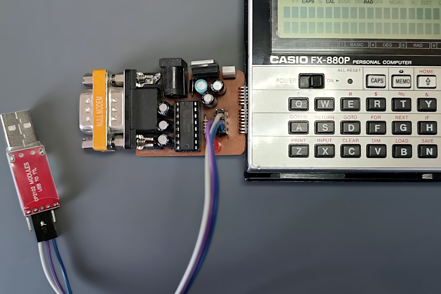
I’d like to point out that in this arrangement, my circuit is doing absolutely nothing. I’m only using the side of the pin header that connects straight to the calculator. Without the jumpers, the entire circuit is effectively disconnected. This is equivalent to connecting the USB adapters right into the calculator port, but with the extra convenience for me that I don’t need to stick bare wires into my calculator, nor count the pins in its connector to get to the right ones.
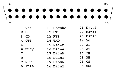
Talking about the right pins, the only signals we need from the USB adapters are RxD (Receive; sometimes labeled just Rx), TxD (Transmit; or just Tx) and GND (Ground). Those are the 3 cables you see in the picture above. Some adapters will include other control signals (plus +5V), but we don’t need them to establish a serial communication to the calculator. The mapping to the FX-8x0P port would be the same I described in my last post, but here it is again, for reference:
Relevant pins are pin 9 (RxD), 14(TxD) and 30(GND).
The Adapters
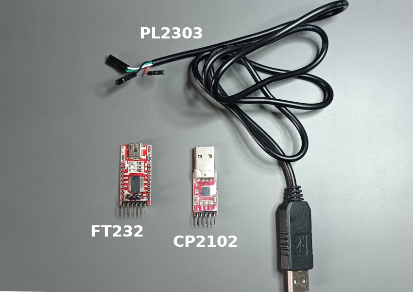
I’ll start with the one based on the PL2303. What I like about this cable is that all the circuitry is packed inside the USB connector side. As it’s an old cable I don’t know if it’s genuine or fake, but the driver wasn’t happy about this one:

I had to install an older version of the driver, from 2008, to make it work. This is a sadly familiar procedure for me. I still have several adapters with Prolific chips, including at least a couple that I’m 99% sure are original, yet they behave the same. The older driver worked without a problem on Windows 10, but I have no idea if it would still work in W11.
After restarting my PC, the Device Manager screen looked like this, and I could continue testing:

Following the standard procedure to save programs from the calculator, I successfully transferred a program to my PC:
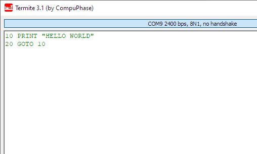
The other two adapters were a lot more straightforward to work with. Despite one of them being an FTDI IC, I didn’t have issues with the driver. Both were recognized successfully and allowed me to transfer a program without any issues.
I was originally worried about potential “signal polarity” issues, but apparently that was only a problem with RS232 to TTL adapters, and not with USB ones. None of the ones I tested now had inverse polarity in any way shape or form, so I would assume it would be unlikely to run into that problem.
Conclusions
Using this information it should be very easy for anyone to build their own cables. It’s just a matter of getting a USB-to-TTL adapter, the 15×2 pin header, and optionally create an enclosure for it. Based on my test the only thing to really pay attention to, is what USB-TTL controller they use. Other than that this should be very straightforward.
As a matter of fact, I’ve been thinking about building USB cables for my calculators for a while. And if I wanted them to look more professional I could make my own PCB with the driver IC, housed inside a custom 3D-printed shell.
One last note; if you test a USB adapter and it doesn’t work, try swapping RxD and TxD. You obviously need to connect the receiving line from the adapter, to the transmitting pin of the calculator and viceversa, so RxD to TxD and TxD to RxD, but sometimes the modules are labeled “device-wise”(that is, “as seen from the other end”) and thus you would need to reverse them, and match the labels.
If you connect them the wrong way nothing bad should happen, except that you won’t see anything being sent or received until you get them right.
Good evening,
thank you for your new article concerning the connection between an FX-850P / 880P and a PC.
I ordered the components…
(see links below)
When my built is working, I will report back here.
Unfortunately, there is no way to post any pictures… but I guess that my construction will be pretty much the same as the one shown on this page.
Cool! I couldn’t actually open the links because they required me to log in and I don’t have an account there (and I removed the links from your comment because they might have contained some session information encoded), but from the URLs they looked right. You don’t need to share pics after your build but I’d be happy to help if you have any problems during the project, and I’d be even more happy to know later, that you succeeded.
Regards~
Hey,
First of all, a Happy New Year!!!
IT WORKS … (well, sort of)
I got the components and was able to “communicate” with the FX850P.
The adapter is recognized as a Silicon Labs CP210x USB to UART Bridge
It is exactly the same as on your picture (CP2102)
But I think I messed up with the settings.
I tried Termie 1.0 and Termite 3.4.
For the transmission Casio-PC, both programs spit out the same garbage. (Nothing to do with the Casio program I try to transmit from the FX-850p to the computer.)
All I get is a long phrase composed of a mix of “ÿ”, “[“, “]” and numbers from 0 to 9, sometimes an “E”.
Settings in Termite: (equivalent in Termie)
Port: COM3
Baud Rate: 2400
Data Bits: 8
Stop Bits: 1
“Parity”, “Flow Control” and “Forward”: none
The rest is all default…
The menu says: COM3, 2400bps, 8N1, no handshake
Are there any other hidden settings I might have overseen?
I have not tried the PC-Casio transmission yet, as I think, once the settings are correct, the transmission in both directions should work.
Any thoughts?
Thanks for a hint of which setting is wrong…
Cheers,
Eric
Got it to work…
no problems!!!
Happy Happy Happy
But I still do not know why it was not working before!!!
Nice! Glad to hear you got it working! Sometimes a bad connection, inverted TX/RX, or a difference in the baud rate can cause those weird characters.
Now have fun loading/saving programs from your calculator, testing programs from the internet and writing your own!
Regards ~
The problem was something “unexpected”…
I used an old “telephone wire” and even if the PVC coating looked perfectly fine, I discovered that inside, the wire was broken. One millisecond, it made contact and the next millisecond, the communication was interrupted.
I was able to make it work correctly only after re-building my setup and using other wires.
Now I am busy experimenting… but the dog waits to go for a walk and my wife starts to give me hints that for today, I have been already enough time in front of the screen…
Regarding programs on the internet… I have not found many … a few games and ASCII editors…
But I am going to have a look on the “internet archive” (books section) …
There must be some old periodicals such as “Chip (magazine)” or “Computer Zeitung”…
Oh I truly hate when wires are “broken” inside but they look fine from the outside. What a tricky problem to diagnose.
I guess it’s becoming harder every day to run into Casio programs in the wild, except maybe in forums and small blogs that are still alive. I remember that 15 years ago there were several places with programs and a lot of info on the FX-8x0P family of calculators. I’d recommend you to expand your search for calculators like the FX-720P or the 820. I actually have a book with programs for these older models, and I’ve tried a couple of them that work with very minimal changes required.
Maybe I should start a collection of useful programs for the FX-880P (not that I have any. But I could start porting them from books)