I’ve been having lots of fun with a Skywatcher telescope I bought a couple of months ago, for which I already built a power pack. The telescope came with a “computerized” GOTO mount that can find and track objects in the night sky, after a simple alignment procedure. For those features to work, however, the telescope needs to know its geographical position and the current date and time.
If you use the Synscan smartphone app, this information is obtained automatically from your phone’s GPS. The app also allows the phone to control the telescope over wifi. This works well, but I heavily dislike the idea of depending on my phone to use the telescope, as it makes it a lot less practical to check any sky map app, take pictures, or just use my phone for anything else. And if my phone runs out of battery then the observing session is immediately over.
The Handset
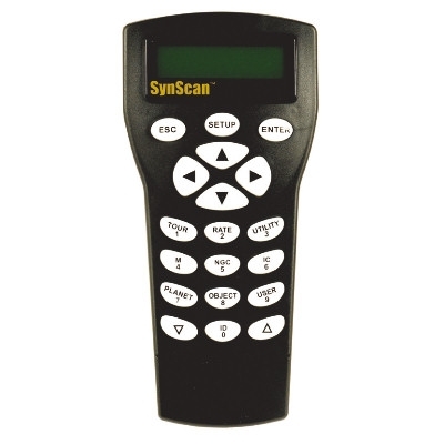
Another alternative is through the Synscan handset. This device is as capable as the phone app, but it’s a simpler device, and doesn’t know its location nor the time of the day, so before alignment, tracking or searching for objects, it asks for that data to be entered using the numeric pad. This might be cumbersome at first but if you are not moving the telescope, you will only need to update the time and date at the beginning of every session, as the coordinates and timezone will be saved. The handset is not cheap, but it’s a good investment, as it gives you a more tactile, phone-free way of controlling the scope. It also comes with some telescope mounts and kits, but in my case I had to buy it separately.
Of course, there’s an alternative to entering that information manually. The handset has a feature to communicate with an external GPS and retrieve that information automatically instead of having to enter it by hand. The problem? The Synscan GPS unit costs like $200 on top of the cost of the handset, as this method requires both.
Having said that, if you already have the handset, you can build the GPS unit yourself. Based on the software used to connect the Synscan GPS to a PC, the official device seems to be a PL-6313 GPS unit, and it should be possible to “emulate” its command set using a more generic GPS module.
In fact, someone by the name of tazounet already made this with just an Arduino, a RS232-TTL converter, a 12V-5V DC-DC module (for power), and of course, a GPS module. The project is open source (which is great), and I happen to have all of those components.
The Hardware
The first thing we need, is to get familiar with the pinout for the 6-pin connector used by the handset to communicate with the GPS unit. This is described in the Synscan manual as the “Multi-Purpose” port:
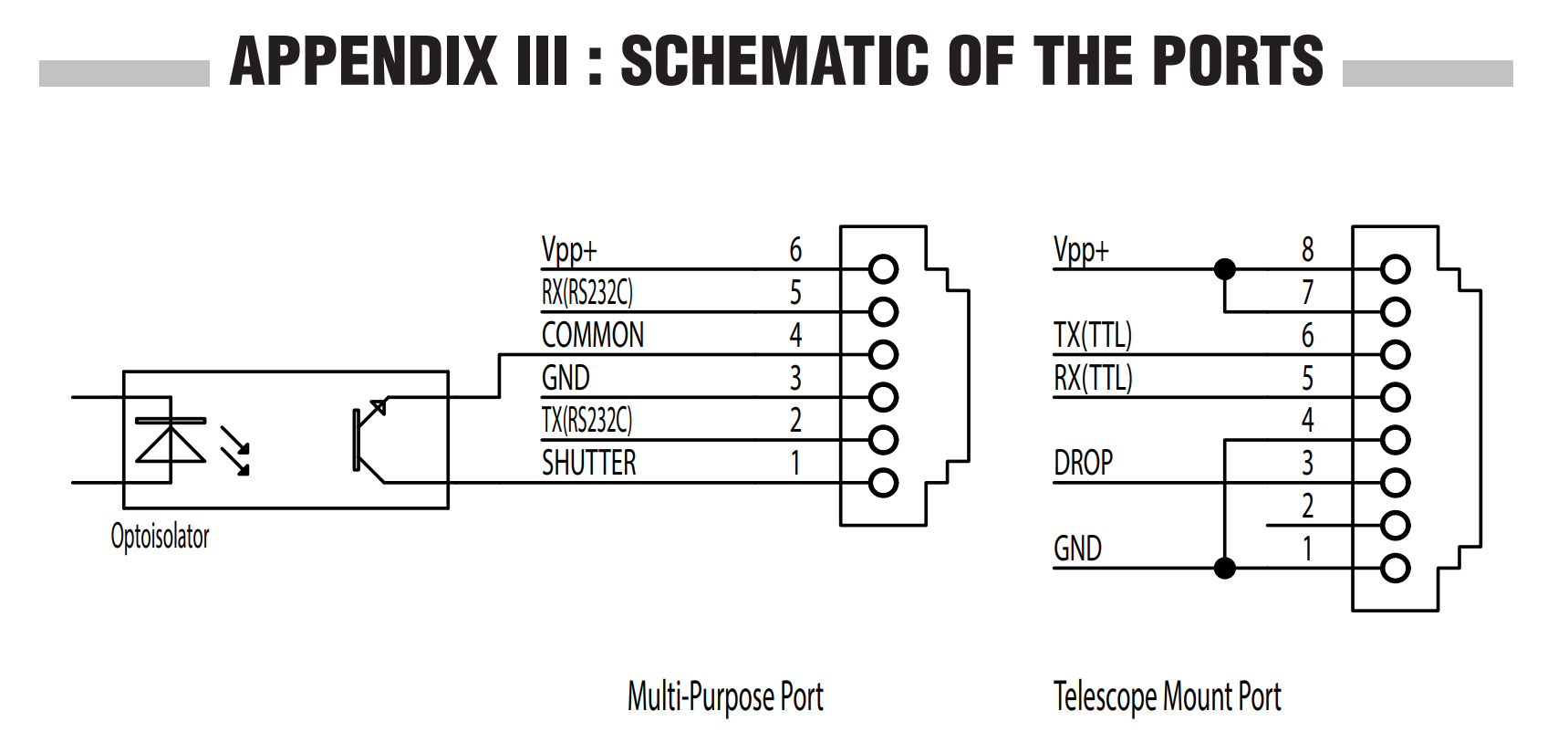
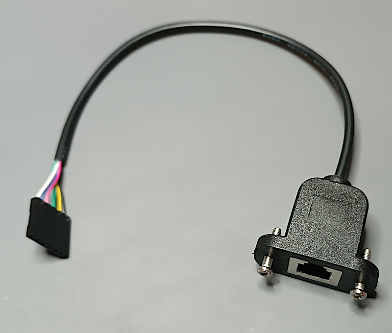
This is a very standard “telephone style” RJ12 connector, but with 6 pins. I got myself a cable (RJ12 6P6C) and a “receptacle” (pictured below) for this project.
From the pinout we can see that the port has Vpp and GND pins; a passthrough for the power it receives from the mount (12V), and it communicates with external devices through RS232 (normally at 12V too). An Arduino uses 5V typically, and it communicates with 0-5V signals (TTL). This is the reason why this project calls for a 12V to 5V DC-DC buck converter, as well as a RS232-TTL adapter.
It’s also interesting to note that the multi-purpose port has the signal for remote shutter control (to command a camera to take pictures periodically), so I’ll take this opportunity to add a shutter port to my version of this project. In theory I only need an audio jack, that according to internet should be wired like this:
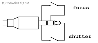
The output of the multi-purpose port is opto-isolated, and should be connected with pin 4 (common) going to the sleeve of the 2.5mm audio connector, and pin 1 (shutter) to the tip of it.
Anyway, to put this project together, this is what I used:
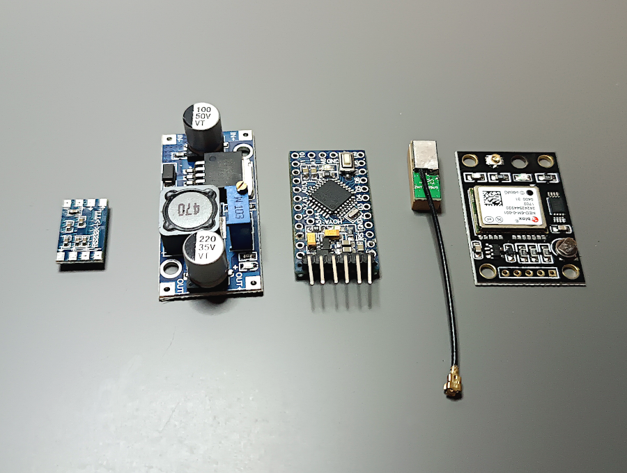
I added other stuff like the audio jack for shutter release, an LED for the GPS “fix” indicator, and a switch to turn the unit off (that’s for when I want to use the box as as shutter control only).
The Software
Tazounet‘s project is relatively simple, but there’s as issue with my GPS module.
The code assumes that the GPS module operates at 4800bps, and I’m using a NEO-6M that by default communicates at 9600bps. Of course the first thing I tried was changing tazounet‘s code so it would talk to the GPS at 9600 baud instead of 4800, but I was getting weird coordinates and time/date information. I suspect that this is because the GPS is sending data faster than the code is retrieving from the Arduino buffer, and some of it is getting lost.
Since that failed, I next tried setting my GPS unit to 4800 bauds, something that can be accomplished with the u-Center software and a USB->TTL adapter. This worked, but only for a while. My GPS module had a very dead battery and wasn’t holding the configuration for more than a couple of hours, so it eventually reverted back to 9600 (its default value). This battery is technically rechargeable so maybe by leaving the module ON for a whole night I could get it back to a decent charge, but if I don’t use it it’ll eventually run low again and return to 9600.
I then tried different things with the code; parsing more bytes from the GPS at a time (which worked, but not consistently enough), and later running the GPS parsing on a timer interrupt, but solutions started to get complex and messy, so I decided to go for the simplest solution, which is adding a bit of code to the initialization that (while communicating with my GPS at 9600 bps), would issue a command to switch to 4800. From that point onward both the GPS and the handset operate at the same baud rate.
For those curious, this is the data you need to send to a uBlox GPS to set it to 4800bps:
{
    0xB5, 0x62, // header
    0x06, 0x00, // class id
    0x14, 0x00, // length in bytes (20)
    0x01,                   // port id
    0x00,                   // reserved0
    0x00, 0x00,             // txReady
    0xD0, 0x08, 0x00, 0x00, // mode (no parity, 1 stop bit, 8 bit data)
    0xC0, 0x12, 0x00, 0x00, // baudrate (4800)
    0x07, 0x00,             // inProtoMask
    0x03, 0x00,             // outProtoMask
    0x00, 0x00,             // reserved4
    0x00, 0x00,             // reserved5
    0xcf,                   // CK_A
    0xe4,                   // CK_B
  };
Now that I was making changes to the code I also made the “fix” LED blink when it’s starting up, so I know it’s alive and looking for satellites.
One last thing to keep in mind is regarding the dependencies for this project. The author seems to have used version 1.41 of the Adafruit GPS library. I tried the last available version but I was having some issues (it was detecting a “fix” prematurely) so I downgraded mine to 1.41 too, as it’s been running fine since.
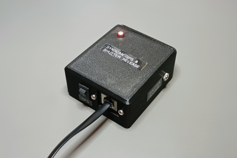
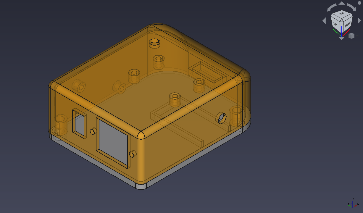
The enclosure
Once I verified that the unit was working, I designed a case for it. I tried to make the enclosure as compact as I could, but since I’m using connectors between the boards, and I have added LEDs, switches, etc, this is a going to be a highly compressed build.
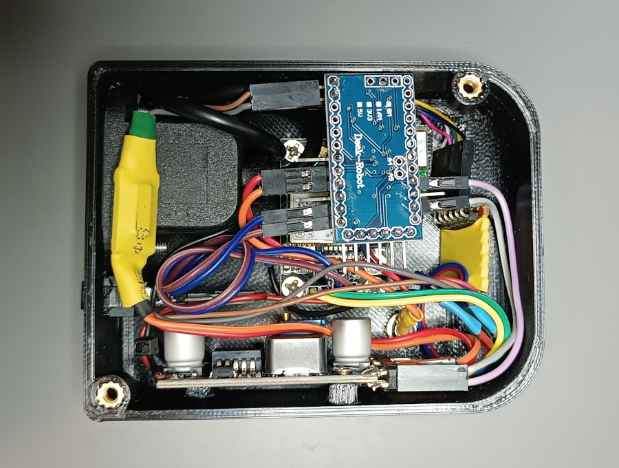
The 3D printed case looks great, and I added some labels so it wouldn’t be a mysterious random box. The GPS side can be turned off to save power once a fix has been obtained, and that leaves the shutter control still available.
The changes to the code I made will probably be available later either on the official repo for the project or in a personal fork. I just want to test them a bit more and make some small adjustments if needed, but I’m extremely grateful to the original author because now I have a working GPS unit for my telescope mount.