I’m in the process of acquiring a telescope that has a motorized mount, and it requires a power supply capable of 12V, 1A. While it can be powered by 8 AA batteries, the actual output voltage of a bunch of batteries is not constant; It varies wildly from fully charged to fully discharged, which means that as the batteries drain, the motors will get less and less power. I would ideally like those 12V to be as solid as possible, to ensure a smooth, consistent operation.
Of course the most reasonable setup for this would be a rechargeable battery pack plus a DC-DC switching converter that would keep the output constant. This could either be in buck, boost, or buck-boost configuration.
After measuring the efficiency and power capabilities of some DC-DC converters I had, I decided to use a simple buck converter with current limiter, which means that my only requirement for a battery pack is to be above 12V (plus 1 or 2 volts of headroom).
One power source that can easily meet that criteria are “cordless” tool battery packs, as they normally are rated well above 12V, and have high capacity and high current ratings (not that I need that, but it’s good to have). After looking at what brands are generally easy to find where I live that feature a good relationship between price and capacity, I settled for Einhell X-Change packs. They are 18V; probably made of 5 cells, meaning their output should range from roughly 15 to 21V.
An image from their website confirms my assumption:

That’s 5 cells right there.
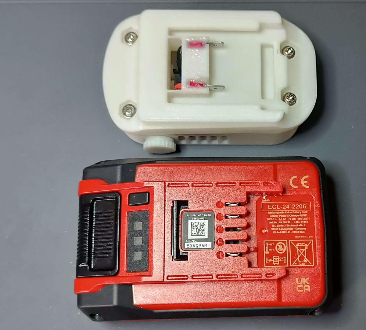
Now I just need to find a way to interface with this battery pack, and for that I found this 3D model on thingiverse:
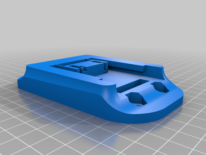
The only minor problem with it, is that it uses M6 screws, which I don’t normally have. As I’ll be mounting a very light device on top, I don’t think the screws need to be that beefy anyway, so I’ll be adapting some M3 screws with spacers and washers to fit there instead.
After printing the piece, I sanded down the inside part of the “rails” a bit so the battery would fit smoothly and lock in place. For the actual electrical connection I followed that project’s recommendation of using spade terminals (pictures of that later).
The Buck converter I selected allows for a max current to be set, that if exceeded, will cause the voltage to drop until the current consumption is brought back within limits, so I set it for 12V, 2A. I am also using a separate buck converter with 5V USB output because I think it’s always a good idea to have a USB port for charging things (like my phone, on which I’ll be running an app to locate stars and planets)
After some measurements and a bit of 3D CAD magic, I made this:
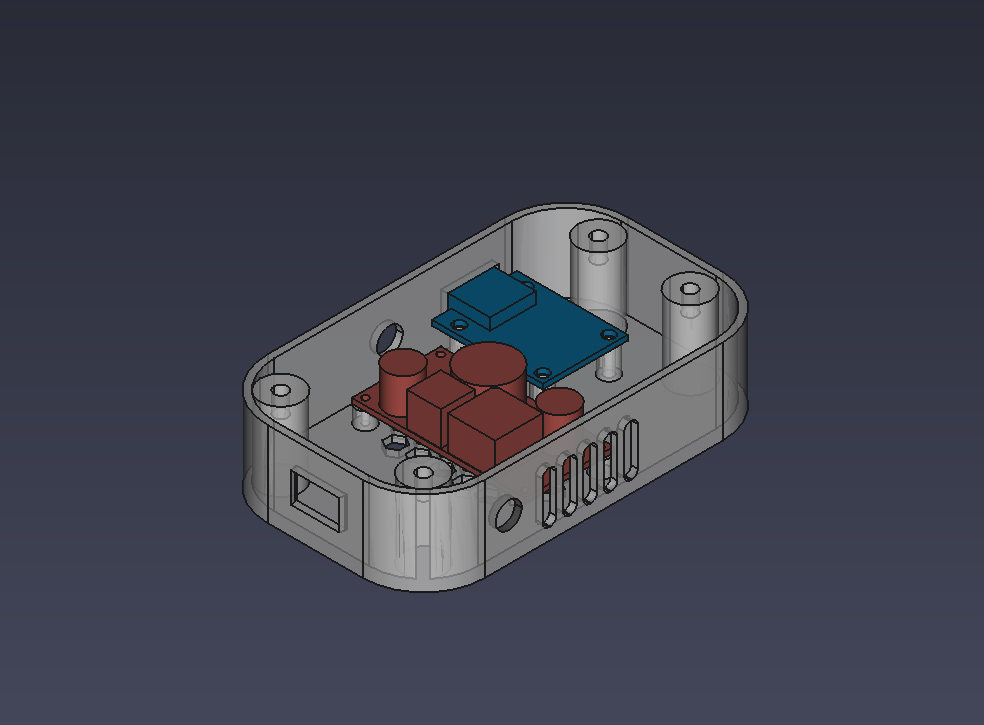
You can see a rough sketch of the buck converter (in red) and the USB adapter (in blue) and how they fit in the case (grey) I designed.
For connecting this to the other piece, I’ll be using knurled M3 brass inserts, and the aforementioned M3 screws with washers, and small plastic spacers that will fit in the M6 holes, centering the m3 screws in place. Not ideal, but should work fine.
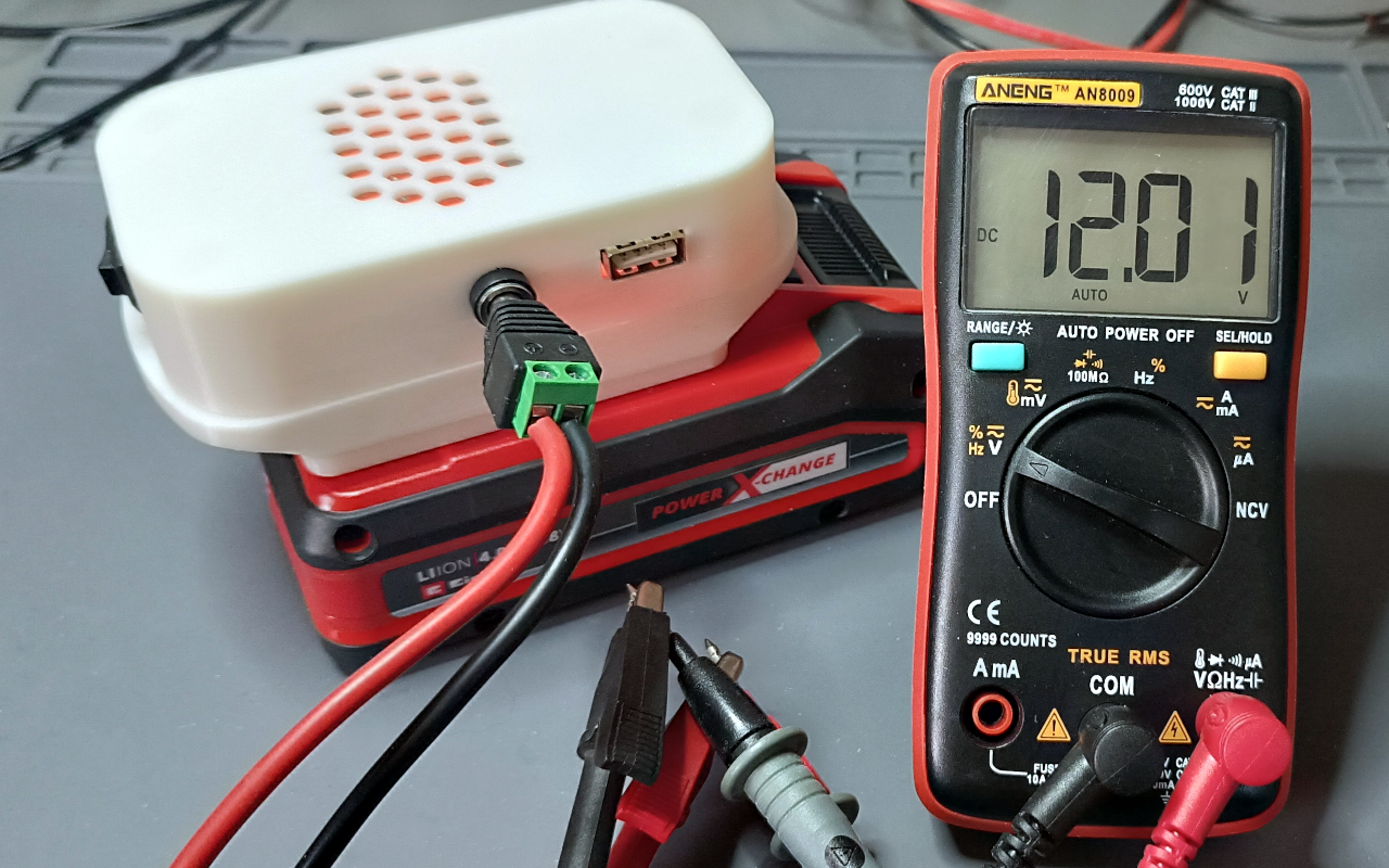
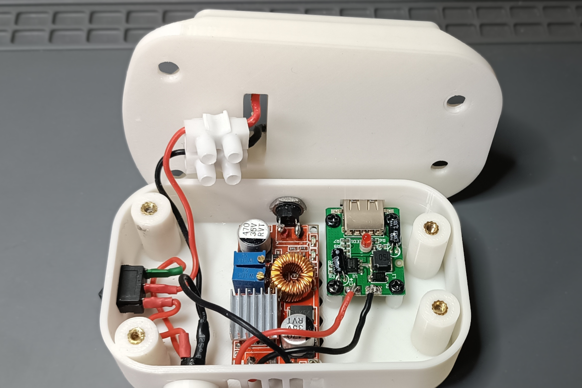
Once printed and soldered, this is what the whole thing looks like:
The underside of it, once assembled:
You may have noticed what looks like a ribbed knob on the other side of the output ports. next to the side ventilation slots. That’s actually another output jack, but with a 3D-printed “cap” on it, to protect it from accidental short circuits. That output provides direct access to the battery pack terminals, and
it’s wired so it’s only connected to the battery when the switch is OFF. When the switch is ON, the direct output jack is disabled, and the 12V and 5V outputs become available. This is for several reasons, but mostly because if I ever need the full 18V straight from the pack, I’d like to have an uninterrupted, unaltered connection to the battery, without wasting power on (or getting inductive noise from) the 12V and 5V buck converters.
The plastic cap is there for extra protection. it’s easy to short-circuit a barrel jack if it comes in contact with the tip of a screwdriver for example, when stored.
I don’t have the same concern with the 12V output, as the DC converter’s current limiting setting provides some protection against short circuits. Plus, the 12V output is only available when the switch is ON, which limits its potential for being short-circuited by a rogue tool when not in use.
I also took the time to measure the turn-on and turn-off characteristics of the DC-DC converter to make it sure it was safe to use, and that no voltage spike would occur if a load is suddenly connected, or if the converter starts or shutdowns while the device is still in line.
I’m yet to receive the telescope, but I wanted to have a suitable portable power source ready by the moment it arrives. If for whatever reason this thing doesn’t work with it, I can always use this device on a different project, as 5V and 12V outputs are a very common requirement.
As a run-time test, I left this device running with a constant current draw of 700mA (according to some online info, the motorized mount will be drawing at most ~350mA when moving all motors simultaneously, but I’m doubling the average consumption to 700mA to account for connecting my phone or other 5V device for charging during observation).
I had to stop the test after 6 hours because I needed to sleep. The built-in battery charge indicator was down to its last light, but I’d assume it would have easily done half an hour more, and I didn’t even start with a fully charged pack.
It follows that for a max power consumption of 350mA, this could easily do 12 hours. That’s already equivalent to like 2 long nights of observation with the motors going non-stop (which is not realistic at all). So I guess that even with some moderate use of the USB port, this is going to last several nights of sky-watching on a single charge.